
Posts

Showing posts from May, 2021

Electrons | Complete notes with short answer questions and numerical problem solutions | Class 12 NEB Physics
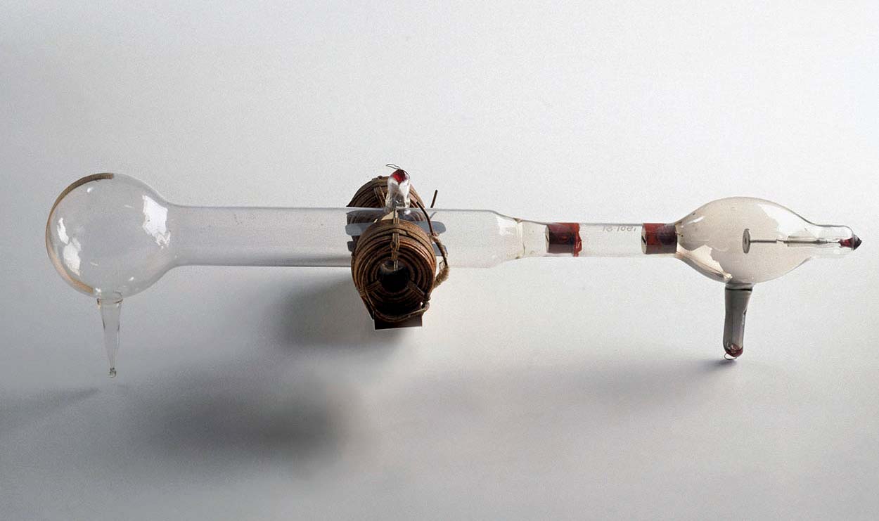
Image
Electrons Introduction and background Electron is the lightest subatomic particle. It carries a charge of -1.602176634 × 10 -19 C, which is considered the fundamental or basic unit of electric charge. The mass of an electron is 9.1093837015 × 10 -19 kg which is \(\frac{1}{1836}\) times the mass of a proton (a positively charged constituent of an atom). Discovery of electrons: The discharge tube experiment played an important role in the discovery of electrons. While studying the properties of cathode rays (1897 A.D.), J.J. Thomson ( Nobel prize for Physics, 1906 ) found that the cathode rays are deflected in electric and magnetic fields which led scientists to believe that the cathode rays are made of tiny negatively charged particles. ( Note! In this chapter, we will learn how the electrons get affected by the electric and magnetic fields so you would know why scientists came in conclusion to identify the discovered particle as negatively charged el

Electrical circuits | Complete notes | Short answer question and numerical problem solutions | Class 12 NEB | Physics in Depth

Image
Electrical Circuits Kirchhoff's law Kirchhoff's junction rule : The algebraic sum of the currents into any junction is zero. i.e., \[\Sigma I = 0\] Alternatively, it can also be stated as, 'the sum of currents entering any junction must be equal to the sum of the currents leaving that junction'. Kirchhoff's loop rule : The algebraic sum of the potential differences in any loop, including those associated with emf s and those of resistive elements, must equal zero. \[\Sigma V=0\] Note that the Kirchhof's junction rule is based on the conservation of electric charge and Kirchhoff's loop rule is based on the conservation of energy. Sign conventions for the loop rule In order to apply Kirchhoff's loop rule in electrical circuit, the following sign conventions should be used: Sign convention for emf s : If the direction of travel (i.e., the direction you chose to travel in a loop ) is from

In the adjacent circuit find: (i) the current in resistor R, (ii) resistance R, (iii) the unknown emf E, (iv) if the circuit is broken at P, what is the current in resistor R?

Image
In the adjacent circuit find: (i) the current in resistor R, (ii) resistance R, (iii) the unknown emf E, (iv) if the circuit is broken at P, what is the current in resistor R? Solution: (i) Using Kirchhoff's junction rule, At junction a, \[\begin{align*} I_1+I_2&=I_3\\ I_1&=I_3-I_2\\ &=6-4\\ \therefore I_1&=2 \hspace{0.1cm} A\\ \end{align*}\] Hence, the current in resistor R is 2 A . (ii) Using Kirchhoff's loop rule, In loop cdefc, \[\begin{align*} -I_1\times R_1 + E_1 - I_3 \times R_3 &=0\\ -2 \times R + 28 - 6\times 3&=0\\ -2 \times R + 28 - 18 &=0\\ -2\times R + 10&=0\\ \therefore R&=5 \hspace{0.1cm} \Omega\\ \end{align*}\] Hence, the resistance R has a value 5 Ω . (iii) Using Kirchhoff's loop rule, In loop cdabc, \[\begin{align*} -I_1 \times R_1 + E_1 - E + I_2\times R_2&=0\\ -2 \times R + 28 - E + 4\times 6&=0\

Using Kirchhoff's laws of current and voltage, find the current in 2 Ω resistor in the given circuit.

Image
Using Kirchhoff's laws of current and voltage, find the current in 2 Ω resistor in the given circuit. Solution: Using Kirchhoff's junction rule, At junction a, \[I_1+I_3=I_2 \hspace{0.1cm} \text{ ... (i)}\] Using Kirchhoff's loop rule, In loop ecdfe, \[\begin{align*} -I_1 \times R_1 + I_3 \times R_3 - E_2 + E_1 &=0\\ -I_1 \times 3 + I_3 \times 4 - 40 + 35 &=0\\ 4I_3 - 3I_1&=5 \hspace{0.1cm} \text{ ... (ii)}\\ \end{align*}\] In loop eabfe, \[\begin{align*} -I_1 \times R_1 - I_2 \times R_2 + E_1&=0\\ -I_1 \times 3 - I_2 \times 2 +35 &=0\\ -3I_1 - 2(I_1+I_3)+35&=0\\ -3I_1-2I_1-2I_3+35&=0\\ -5I_1-2I_3+35&=0\\ 5I_1+2I_3&=35 \hspace{0.1cm} \text{ ... (iii)}\\ \end{align*}\] Multiplying equation (iii) by 2 and subtracting (ii) from (iii), we get, \[\begin{align*} 4I_3+10I_1-70-(4I_3-3I_1-5)&=0\\ 13I_1&=65\\ \therefore I_1&=5 \hspace{0.1cm} A\\ \

What must be the emf E in the circuit so that the current flowing through the 7 Ω resistor is 1.80 A? Each emf source has negligible internal resistance.

Image
What must be the emf E in the circuit so that the current flowing through the 7 Ω resistor is 1.80 A? Each emf source has negligible internal resistance. Solution: Given, Current through 7 Ω resistor, \(I_3\) = 1.80 A Using Kirchhoff's junction rule, At junction a, \[\begin{align*} I_1+I_2&=I_3\\ I_1+I_2&=1.80 \hspace{0.1cm} \text {... (i)}\\ \end{align*}\] Using Kirchhoff's loop rule, In loop ecdfe, \[\begin{align*} -I_3 \times R_3 - I_1 \times R_1 + E_1 &=0\\ -1.80 \times 7 - I_1 \times 3 +24 &=0\\ -12.6 - 3I_1 +24&=0\\ 3I_1&=11.4\\ \therefore I_1&=3.8 \hspace{0.1cm} A \\ \end{align*}\] From equation (i), \[I_2=1.80-3.8=-2 \hspace{0.1cm} A\] In loop eabfe, \[\begin{align*} -E+I_2\times R_2 - I_1 \times R_1 + E_1&=0\\ -E+(-2) \times 2 - 3.8 \times 3 +24 &=0\\ -E-4-11.4+24&=0\\ \therefore E&=8.6 \hspace{0.1cm} V\\ \end{align*}\] Hence,

A potentiometer is 10 m long. It has a resistance of 20 Ω. It is connected in series with a battery of 3 V and a resistance of 10 Ω. What is the potential gradient along with wire?

Image
A potentiometer is 10 m long. It has a resistance of 20 Ω. It is connected in series with a battery of 3 V and a resistance of 10 Ω. What is the potential gradient along with wire? Solution: In figure, AB is a potentiometer wire. length of potentiometer wire, \(L\) = 10 m resistance of potentiometer wire, \(R_{AB}\) = 20 Ω resistance in series, \(R\) = 10 Ω potential gradient , \(k\) = ? total current flowing through the wire is, \[\begin{align*} I&=\frac{E}{R+R_{AB}}\\ &=\frac{3}{30}\\ \therefore I&=0.1 \hspace{0.1cm} A\\ \end{align*}\] Now, potential drop across AB is, \[\begin{align*} V&=I R_{AB}\\ &=0.1 \times 20\\ \therefore V&=2 \hspace{0.1cm} V\\ \end{align*}\] So, the potential gradient along with the wire is, \[\frac{V}{L}=\frac{2}{10}=0.2 \hspace{0.1cm} V/m\]

A simple potentiometer circuit is setup as in fig., using uniform wire AB, 1.0 m long, which has a resistance of 2 Ω . The resistance of the 4 V battery is negligible. If the variable resistor R were given a value of 2.4 Ω, what would be the length AC for Zero galvanometer deflection?

Image
A simple potentiometer circuit is setup as in fig., using uniform wire AB, 1.0 m long, which has a resistance of 2 Ω . The resistance of the 4 V battery is negligible. If the variable resistor R were given a value of 2.4 Ω, what would be the length AC for Zero galvanometer deflection? Solution: Given, length of potentiometer wire, \(L\) = 1.0 m resistance of potentiometer wire, \(R_{AB}\) = 2 Ω emf of driving cell, \(V_0\) = 4 V variable resistance, \(R\) = 2.4 Ω balancing length, \(l\) = ? For balancing length, potential difference across potentiometer wire is equal to p.d. across cell. So, we first calculate p.d. across wire. Current through wire is, \[\begin{align*} I&=\frac{V_0}{R_{AB}+R}\\ &=\frac{4}{4.4}\\ \therefore I&=0.91 \hspace{0.1cm} A\\ \end{align*}\] Then p.d. across wire is, \[\begin{align*} V_{AB}&=I \times R_{AB}\\ &=0.91 \times 2\\ \therefore V_{AB}&=1.82 \hspace{

The total length of the wire of a potentiometer is 1.0 m. A potential gradient of 0.0015 V/cm is obtained when a steady current is passed through this wire. Calculate, (i) the distance of the null point on connecting standard cell of 1.018 V. (ii) the unknown p.d. if the null point is obtained ata distance of 940 cm, and (iii) the maximum p.d. which can be measured by this instrument.

The total length of the wire of a potentiometer is 1.0 m. A potential gradient of 0.0015 V/cm is obtained when a steady current is passed through this wire. Calculate, (i) the distance of the null point on connecting standard cell of 1.018 V. (ii) the unknown p.d. if the null point is obtained ata distance of 940 cm, and (iii) the maximum p.d. which can be measured by this instrument. Solution: Given, length of potentiometer wire, \(L\) = 10 m potential gradient, \(k\) = 0.0015 V/cm = 0.15 V/m (i) \(l\) = ?, \(E\) = 1.018 V For null point, potential across potentiometer wire should be equal to that of standard cell. \[\begin{align*} V&=E=kl \\ 1.018&=0.15 \times l\\ \therefore l&=6.78 \hspace{0.1cm} m\\ \end{align*}\] (ii) \(l\) = 940 cm = 9.40 m , \(V\) = ? \[\begin{align*} V&=kl\\ &=0.15 \times 9.40\\ &=1.41 \hspace{0.1cm} V\\ \end{align*}\] (iii) Maximum potential dif

The driver cell of a potentiometer has an emf of 2 V and negligible internal resistance. The potentiometer wire has a resistance of 3 Ω. Calculate the resistance needed in series with a wire if a p.d. 5.0 mV is required across the whole wire. The wire is 100 cm long and a balanced length of 60 cm is obtained for a thermocouple of emf E. What is the value of E?

Image
The driver cell of a potentiometer has an emf of 2 V and negligible internal resistance. The potentiometer wire has a resistance of 3 Ω. Calculate the resistance needed in series with a wire if a p.d. 5.0 mV is required across the whole wire. The wire is 100 cm long and a balanced length of 60 cm is obtained for a thermocouple of emf E. What is the value of E? Solution: emf of driver cell, \(V_0\) = 2 V resistance of potentiometer wire, \(R_{AB}\) = 3 Ω resistance to be connected in series, \(R\) = ? p.d. across AB, \(V\) = 5 mV = 5 × 10 -3 length of potentiometer wire, \(L\) = 100 cm balancing length for thermoemf , \(l\) = 60 cm thermoemf, \(E\) = ? Note that! For the first case just look at the upper section of the figure and for the next part you have to consider the thermocouple (indicted by V in the diagram) that generates thermoemf E. For first part, Since \(R\) and \(R_{AB}\) are in series, the total resistance

The emf of a battery A is balanced by a length 75 cm on a potentiometer wire. The emf of a standard cell 1.02 V is balanced by a length of 50 cm. What is the emf of A?

The emf of a battery A is balanced by a length 75 cm on a potentiometer wire. The emf of a standard cell 1.02 V is balanced by a length of 50 cm. What is the emf of A? Solution: Given, balancing length for battery A, \(l_A\) = 75 cm balancing length for battery B, \(l_B\) = 50 cm emf of battery A, \(\mathcal{E}_A\) = ? emf of battery B, \(\mathcal{E}_B\) = 1.02 V Now, \[\begin{align*} \frac{\mathcal{E}_A}{\mathcal{E}_B}&=\frac{l_A}{l_B}\\ \mathcal{E}_A&=1.02 \times \frac{75}{50}\\ \therefore \mathcal{E}_A&= 1.53 \hspace{0.1cm} V\\ \end{align*}\] Hence the emf of battery A is 1.53 V .